Linked Electronics Co., Limited is a professional PCB and PCBA service provider for 20 years. Our professional OEM electronic manufacturing services impress our customers in various fields around the world. Since its establishment in 2002, Linked Electronics has accumulated a group of engineers with more than ten years of manufacturing experience and professional electronic components purchasing team. With ten years of professional spirit, providing professional engineering services (PCB layout design, SMT process technology solutions, etc.), PCB manufacturing , electronic components purchase, supply chain management, PCBA manufacturing (SMT and DIP), one stop integrated manufacturing service from test, maintenance, aging test and assembly to directional development. Our more than 800 employees are proud to serve customers all over the world in various fields including military electronics, aerospace, medical equipment, industrial automatic control, new energy, automotive electronics, wearable device, 5G communication, drone and LED display, etc. More than 1500 customers have witnessed our growth over the past 20 years.
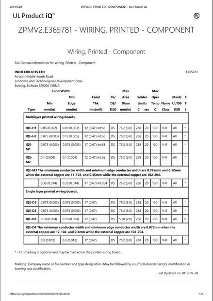
We have 10000 square meters of dust-free workshop and more than 800 employees, more than 30 production lines including PCB manufacturing, SMT, DIP, automatic welding, aging test and assembly etc. The equipment includes over 50 SMT machines from Japan and Korea, automatic solder paste printing machine, automatic stencil test machine, automatic stencil cleaning machine, automatic first sample test machine, SPI solder paste on-line detector, 12 temperature reflow soldering machine, on-line AOI detector, X-ray detector, lead-free wave soldering machine, automatic DIP machine, automatic PCB splitting machine, PCBA auto clean machine, automatic coating machine, intelligent MES electronic material management system etc., with a daily output of 40 million points. A variety of production line configuration can meet all kinds of demands from sample order (lead time 24-hours) to mass production delivery. Our products have passed through many testing procedures, strictly implemented the quality system standards. We have obtained ISO9001, ISO14001, IATF16949 series of system certification and recognized as a national high-tech enterprise. Since the establishment of the company, we are committed to end-to-end one-stop manufacturing solutions. With rigorous technology, excellent quality and fast delivery, we have provided customers with the most convenient and mutually beneficial electronic manufacturing services, and won praise from domestic and oversea markets.

What is the definition of Multilayer PCB electronic printed circuit board?
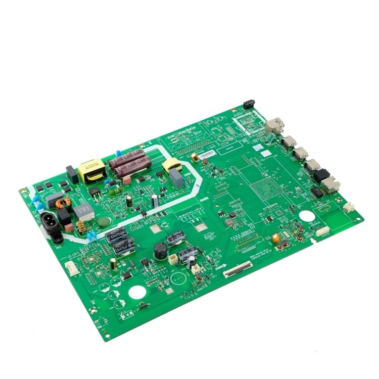
Multilayer PCB is the multi-layer printed circuit board that is composed of three or more electronic layers. This is made up of a substrate layer, which has a conductive metal on top and bottom sides. It also offers enhanced functionality. They are utilized in complex devices which require a very high number of connections.
Multilayer PCB boards includes at least three layers of conductive layers. This multilayer PCB laminating process means pressing FR4 core and PP together.
Both of them are laminated under high hydraulic press pressure and temperature condition. This process will melt prepreg which later make the prepreg to join these layers together.
|
item
|
value
|
|
Model Number
|
Custom Model
|
|
Type
|
consumer electronics pcba
|
|
Place of Origin
|
China
|
|
|
Guangdong
|
|
Brand Name
|
Linked
|
|
Supplier Type
|
PCBA Assembly manufacturer
|
|
Copper Thickness
|
2 OZ
|
|
Product Type
|
Custom HDI PCB
|
|
Service
|
One-stop Turnkey
|
|
Application
|
Electronics Device/Home Application
|
|
Testing Service
|
AOI X-Ray Function Test
|
|
Material
|
FR4/CEM-1/CEM-3/FR1/aluminum
|
|
Board Thickness
|
0.2mm-7.0mm
|
|
Layer
|
1-58 Layers
|
|
Solder mask color
|
Blue.green.red.black.white.etc
|
|
Surface Finishing
|
HASLOSPimmersion Gold
|
|
Certificate
|
ISO9001/Iso14001/CE/ROHS
|
Multilayer PCB Manufacturing Steps
The manufacturing process of multilayer circuits takes several complicated steps which much more difficult and complex than doubled sided PCBs.
PCB Layout--That is the process by customer engineer
Printed Circuit boards should be rigorously compatible with, a PCB layout created by the engineer designer using PCB design software. Here is some of the commonly-used PCB EDA software, Altium Designer, OrCAD, Pads, KiCad, Eagle etc. NOTE: Before the PCB fabrication, designers should inform their contract manufacturer about the PCB design software version used to design the circuit since it helps avoid issues caused by discrepancies.
Once the PCB design is approved for production, designers export the design into format that PCB manufacture accepts and the frequently used program is called extended Gerber in the format IX274X.
The PCB industry birthed extended Gerber as the perfect output format. Different PCB design software possibly calls for different Gerber file generation steps, they all encode comprehensive vital information including copper tracking layers, drill drawing, apertures, component notations and other options. All aspects of the PCB design undergo checks at this point. The software performs oversight algorithms on the design to ensure that no errors go undetected. Designers also examine the plan with regard to elements relating to track width, board edge spacing, trace and hole spacing and hole size.
After a thorough examination, designers forward PCB file to PC Board Houses for production. To ensure the design fulfills requirements for the minimum tolerances during manufacturing process, almost all PCB Fab Houses run Design for Manufacture (DFM) check before printed circuit board fabrication.
Printing of the PCB Design
PCB printing begins after designers output the PCB schematic files and manufacturers conduct a DFM check. The PCB manufacturers use a printer called a plotter, which makes photo films of the PCBs, to print circuit boards. PCB manufacturers will use the films to image the PCBs. Although it's a laser printer, it isn't a standard laser jet printer. Plotters use incredibly precise printing technology to provide a highly detailed film of the PCB design.
The final product results in a plastic sheet with a photo negative of the PCB in black ink. For the inner layers of PCB, black ink represents the conductive copper parts of the PCB. The remaining clear portion of the image denotes the areas of non-conductive material. The outer layers follow the opposite pattern: clear for copper, but black refers to the area that'll be etched away. The plotter automatically develops the film, and the film is securely stored to prevent any unwanted contact.
Each layer of PCB and solder mask receives its own clear and black film sheet. In total, a two-layer PCB needs four sheets: two for the layers and two for the solder mask. Significantly, all the films have to correspond perfectly to each other. When used in harmony, they map out the PCB alignment.
To achieve accurate alignment of all films, registration holes should be punched through all films. The exactness of the hole occurs by adjusting the table on which the film sits. When the tiny calibrations of the table lead to an optimal match, the hole is punched. The holes will fit into the registration pins in the next step of the imaging process.
Print the Copper Utilized for the Interior Layer
This step is the first while making the inner layer of the PCB. You print the multilayer PCB design; then copper is re-bonded to the FR4 or PP that serves as the PCB structure.
Discard unwanted copper
With the photo resist removed and the hardened resist covering the copper that needs to be kept, the board manufacturing steps into the next stage: unwanted copper removal. Just as the alkaline solution removed the resist, a more powerful chemical preparation wash away the excess copper. The copper solvent solution bath removes all of the exposed copper. Meanwhile, the desired copper remains fully protected beneath the hardened layer of photo resist.
Not all copper boards are created equal. Some heavy copper boards require larger amounts of copper solvent and varying lengths of exposure. As a side note, heavier copper boards require additional attention for track spacing. Most standard PCBs rely on similar specification.
Now that the solvent removed the unwanted copper, the hardened resist protecting the preferred copper needs washing off. Another solvent accomplishes this task. The board now glistens with only the copper substrate necessary for the PCB.
Lamination of the PCB Layers
AOI will be performed to check that there will be zero defects for the traces. Those can be bonded together. You can achieve this process in two spes, which includes the lay-up and the laminating.
The entire operation undergoes an automatic routine run by the bonding press computer. The computer orchestrates the process of heating up the stack, the point in which to apply pressure, and when to allow the stack to cool at a controlled rate.
Drilling
Before you drill, the drill spot is located with an x-ray machine. This helps in securing the PCB stack.
PCB Plating
This process helps in fusing the different PCB layers making use of a chemical.
Imaging and Plating of the Outer Layer
By doing this you are guarding the copper found on the outer layer by applying the photoresist.
Final Etching
To protect the copper during the process, a tin guard is utilized. This gets rid of unwanted copper. This also ensures properly established PCB connections.
Applying Solder Mask
After cleaning the PCB panels, soldermask is applied onto both sides of the PCBs
Silk print is printed onto the PCBs
The nearly completed board receives ink-jet writing on its surface, used to indicate all vital information pertaining to the PCB. The PCB finally passes onto the last coating and curing stage.
Electrical and Testing Reliability
A technician performs electrical tests on the PCB. The automated procedure confirms the functionality of the PCB and its conformity to the original design. At linked electronics, we offer an advanced version of electrical testing called Flying Probe Testing, which depends on moving probes onto the pads to test electrical performance of each net on a bare printed circuit board. Another advanced testing is fixture which is faster but expensive for prototypes. The pins of the fixture will touch the pads and check the conformity of the boards.
Mechanic Process
PCBs will be routed as per customer’s mechanic file after flying probe test. For PCB using fixture test, the PCB will be routed out before mechanic process.
FQC
Final inspection will be performed. This includes board thickness, board warp and twist, any scratches etc. The errors rectified before it is sent for delivery.
Materials Used in the Manufacturing of Multilayer PCB
The different materials utilized in manufacturing multilayer PCBs are boards, copper foil, resin system, substrate, infused fiberglass sheet. Using an alternating sandwich, you can laminate these materials together.
All the planes of copper are etched and the plating through of all internal vias is done before the layers.
Multilayer PCB: Advantages
Multilayer PCBs come with lots of great benefits. Some of them include:
• Higher assembly density
• Provision of high speed and high capacity, as a result of their electrical properties
• Weight reduction of devices
• Elimination of connectors needed for multiple separate PCBs, thereby simplifying its construction.
Multilayer PCB: Product Use
Multilayer PCBs can be used in many areas
They are used in manufacturing CAT scan, heart monitors, and modern x-ray equipment.
• Utilized in the production of high-speed circuits due to their functionality and durability
• Used for headlight switches and onboard computers due to their high functionality and heat resistant ability
• The running of machinery and industrial control system utilize them due to their small size and durability.
• Consumer electronics such as microwaves and smartphones also make use of multilayer PCBs as a result of their small size and functionality.
• Satellite applications, GPS, and signal information, also make use of multilayer PCBs
• Used in the production of computer electronics that are utilized in motherboard servers due to its performance and space-saving attributes.
 Your message must be between 20-3,000 characters!